

Investigation of induction heating system
Investigation of induction heating system: Abstract. The aim of the work is the investigation of the induction heating system used for longitudinal, high-frequency pipe welding. Coupled electromagnetic and temperature field distribution has been studied in order to estimate system efficiency and factors influencing the quality of the welding process and required energy. The problem was considered three-dimensional.
Investigation of induction heating system:INTRODUCTION
Investigation of induction heating system: Technologies based on induction heating are widely used in industry due to their advantages: high energy efficiency, excellent product quality, very good accuracy in heating of certain zones in a short time, clean operating conditions. Induction heating has a great variety of industrial applications: induction hardening, induction tempering, induction brazing, induction bonding, induction welding, induction annealing, induction pre and post-heating, induction forging, induction melting, induction straightening, induction plasma production, etc.
The object of the study in this investigation is an induction heating system, used for high-frequency longitudinal pipe welding. The aim of the research and motivation for carrying out the work is the necessity of developing, analyzing, and estimating the system. The main task is to define and then determine optimal factors and parameters influencing the welding process quality and required energy. The detailed determination and understanding of the processes in the device give good possibilities for efficient control, management of the welding process, and energy consumption monitoring.
The analysis of such systems, both theoretical and experimental is focused on frequency, welding speed, “heat-affected zone”, ‘vee’ angle, ferrite impeder presence, and its position. Although there are a number of publications devoted to this topic, the processes in high-frequency welding are still not studied well enough and many interactions and dependencies are not clear.
This is not only because the processes are very complicated, but also because of specific differences of different systems, concerning dimensions, material properties, and the purpose of the welded pipes.
DESCRIPTION OF THE INVESTIGATED INDUCTION HEATING SYSTEM
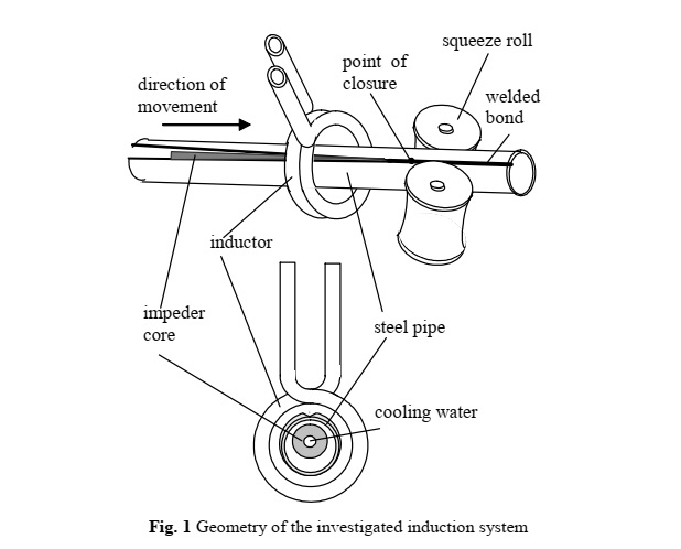
Investigation of induction heating system: The principal geometry of the investigated system is shown in Fig. 1. The system consists of a high-frequency spiral inductor, which induces a voltage across the edges of the open steel pipe. The induced voltage causes high-frequency currents, concentrated on the surface layer due to
the skin and proximity effects. The currents flow along the edges to the point where they meet (point of closure), causing rapid heating of the metal. The weld squeeze rolls are used to apply pressure, which forces the heated metal into contact and forms a welding bond.
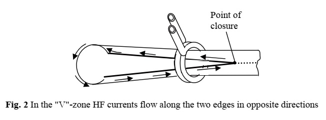
Special attention has to be paid to the “heat-affected region” (Fig.2). In the so-called “V”- zone, due to the skin effect and proximity effect, high-frequency currents flow at high densities along surfaces in opposite directions and seek adjacent parallel surfaces for its return path.
Analysis of Induction Heating System for High-Frequency Welding
The system includes also an inner ferrite impeder, which concentrates magnetic flux and improves the welding efficiency. As it can be seen from geometry in Fig.1, the impeder is located not along the pipe axis, but moved closer to the welded region – i.e. the system is not axisymmetric and the field distribution problem has to be analyzed as three dimensional.
The cooling water flows inside the inductor and impeder for system cooling. The investigation of the system is carried out for the inductor parameters shown in Table 1:
The pipe material is steel with about 10% carbon. The end heating temperature must be about 130014500C. The cooling water flowing inside the conductors is at a temperature of 400C. The temperature of ambient air and the initial temperature of the heated pipe is T0=200C.
MATHEMATICAL MODEL OF THE COUPLED FIELD PROBLEM
As it has been already described the geometry of the investigated system is very complex, and nonsymmetric, so the mathematical model of the object has to be considered as three-dimensional. The study of the processes in the system includes the determination of the electromagnetic and thermal field distribution – the task is coupled field problem. Thus the present work deals with modeling the 3D time-harmonic electromagnetic field. The electromagnetic field problem has been studied not only in the system elements but also in the wide buffer zone around the device. It helps to define correct boundary conditions in field modeling. The eddy current losses, obtained in electromagnetic field analysis are field sources in modeling the transient thermal field.
Investigated regions and domains
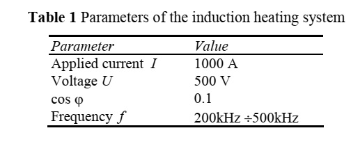
The investigated region used in electromagnetic field modeling is shown in Fig.3. It includes domains: 1- inductor; 2- impeder; 3- welded pipe; 4- cooling water; 5- buffer zone with air.
Basic equations
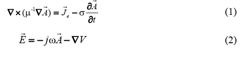
Electromagnetic field distribution can be described with equations (1) and (2):

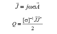
The boundary conditions are taken to be flux-parallel for the buffer zone boundaries. The time-varying electromagnetic field produces eddy currents (3) and corresponding Joule losses (4) – the source of heating in the region:
Analysis of Induction Heating System for High-Frequency Welding
The transient thermal field is modeled by the equation:
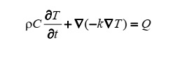
where k is thermal conductivity, T is temperature, is density, C is specific heat and Q is a heat source, obtained in electromagnetic field analysis. The convection boundary conditions are posed both for the outer boundaries of the inductor and the pipe and water cooling of the inner inductor boundaries:
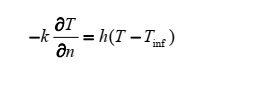
where h is the heat transfer coefficient, Tinf is the external bulk temperature, n is the normal vector of the boundary.
FEM ANALYSIS – NUMERICAL SIMULATIONS AND RESULTS
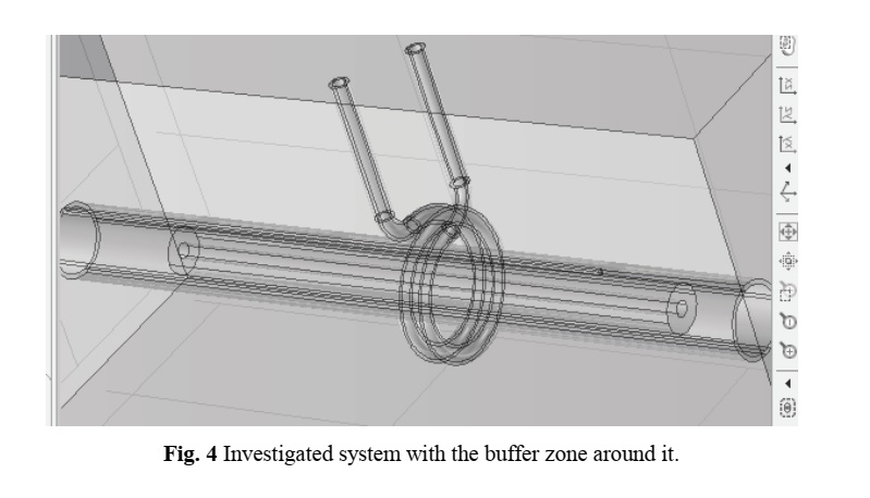
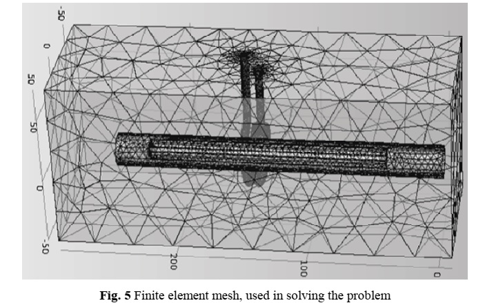
Numerical simulation of the 3D coupled – electromagnetic and thermal fields was carried out using FEM and COMSOL 4.2 package. Fig.4 is shown the investigated system with the buffer zone around it and Fig. 5 presents the finite element mesh, used in solving the problem.
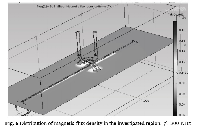
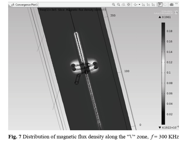
Some results, obtained in solving the problem for frequency 300 kHz are shown in Fig. 6, Fig. 7, Fig. 8, Fig. 9, and Fig. 10. The analysis of electromagnetic field distribution indicates that the maximal value of the magnetic flux density is about 0.19T. These values are reached in the “V” zone and around the inductor. Two different cross-sections illustrate the distribution of the magnetic flux density in the system in Fig.6 and Fig.7.
The results obtained for the current density distribution in the region are shown in Fig.8.
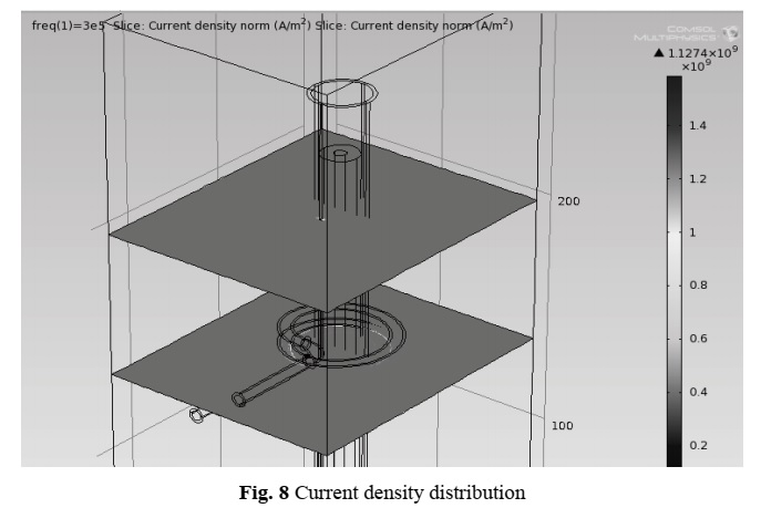
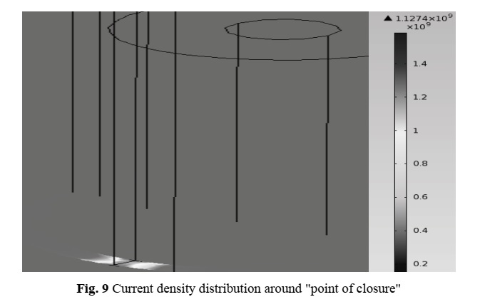
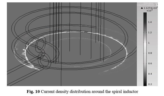
Two specifics for the problem cross-sections – around “point of closure” and spiral inductors are picking out. The maximal value is 1.13109 A/m2. The current density distribution around the “point of closure” is shown in Fig. 9 and in Fig. 10 around the spiral inductor.
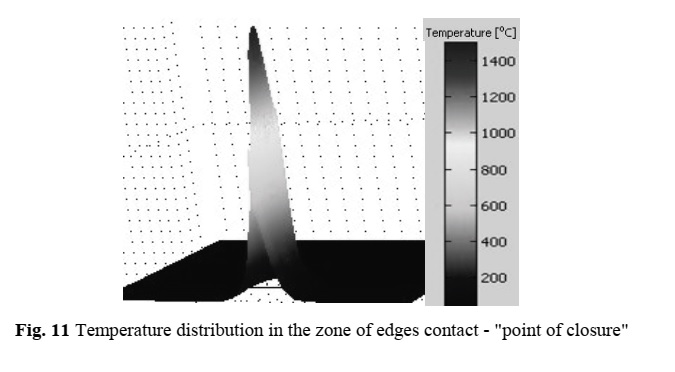
The results for temperature distribution in the zone of edges contact – around the “point of closure” are shown in Fig.11. In this zone, the temperature value increased to 1400 °C.
CONCLUSION
Determination of electromagnetic and temperature field distribution of induction heating system used for longitudinal pipe welding has been obtained. The problem was considered as 3D, coupled–time harmonic electromagnetic and transient thermal field. It has been solved using the finite element method and COMSOL 4.2 software.
The detailed determination of field distribution in the studied device is a tool for subsequent efficient control, management of the welding process, and energy consumption monitoring.
REFERENCES
[1] N. Gluhanov and V. Bogdanov, “Welding of metals using high-frequency heating”, Moscow, 1962.
[2] A. Shamov, I. Lunin, and V. Ivanov, “High-frequency metal welding”, Mashinostroenie, Leningrad, 1977.
[3] J. Davies and P. Simpson, Induction heating handbook, McGraw-Hill Book Company (UK) Ltd.,1979.
[4] www.edf-induction.com/en/InducctionNews/Articles.aspx.
[5] R. Baumer and Y. Adonai, “Transient High-Frequency Welding Simulations of Dual-Phase Steels”,
Welding Journal, vol. 88, pp. 193 – 201, 2009.
[6] D. Kim, T. Kim, Y.Park, K.Sung, M.Kang, C.Kim, I.Lee, and S.Rhee, “Estimation of Weld Quality in
High-Frequency Electric Resistance Welding with Image Processing”, Welding Journal, vol. 86, no. 3,
pp. 27 – 31, 2007.
[7] B. Grande, O. Waerstad and P. Runeborg, “Weld Setup, Variable Frequency and Heat Affected Zones in
High-Frequency Tube and Pipe Welding”, Tube and Pipe Technology, pp. 116-119, 2012.
[8] B. Grande and J. Asperheim, “Factors Influencing Heavy Wall Tube Welding”, Tube and Pipe
Technology, pp. 86-88, 2003,
[9] P. Yan, O. Gungor, P. Thibaut, M. Liebeherr, and H. Bhadeshia, “Tackling the Toughness of Steel Pipes
Produced by High-Frequency Induction Welding and Heat-Treatment”, Materials Science and
Engineering: A, vol. 528, no. 29-30, pp. 8492 – 8499, 2011.
[10] A. Spahiu, “Experimental Study of the Induction Heating in the Manufacturing of Metallic Tubes by
Longitudinal Welding Process”, U.P.B., Sci. Bull., Series C, No.2, 2007.
[11] COMSOL Version 4.2 User’s Guide, 2011.


No comment